
0
Owner's of the ACR Electronics Marine Lighting 3940.1 gave it a score of 0 out of 5. Here's how the scores stacked up:

5
Y1-03-0165 Rev. D
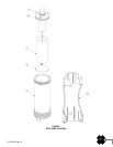
2.3 Disassembly
This will ordinarily be required only if testing shows that the light is malfunctioning, or if battery replacement is required.
Recommended interval for battery replacement is one year.
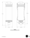
A. Hold the unit on a flat, firm surface, lens side up. Depress the top cap of the unit, by pushing straight down on
the top cap assembly, until the swivel locks may be turned outward, clear of the cap.
B. Grip the light lens (using a clean cloth or gloves for a better grip on the smooth surface and to avoid marring
the lens surface) and pull upwards until the top cap is clear of the case.
C. Turn the unit on its side, open end slightly downwards, to allow the foam filler and battery to slide out.
D. Disconnect the battery by unscrewing the terminals from the battery posts.
E. Replace the strobe module, if required, as follows:
a. Remove foam filler from strobe module, by sliding it off.
b. Slip foam spacer over new strobe module to seat in cap recess.
c. Inspect O-Ring seal for proper fit. Lubricate with silicone grease.
F. Replace the battery by securing the two terminals to the battery posts. Assure tightness.
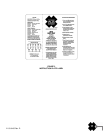
NOTE: Connect black lead to center (-) post of battery. Connect red lead to outer (+) post of battery.
G. Check for proper operation by holding the top cap assembly vertical (light lens up). The unit should flash
about once each second. If the unit does not operate, check for proper battery connection.
2.4 Assembly
A. Hold the case horizontally and slide the battery in, terminal end up (towards the open end of the case).
B. Lubricate the top cap O-ring with silicone grease and insert the cap and foam spacer into the case.
C. Place the unit upright on a firm surface, and press the top cap assembly until the cap slips into the case.
D. Depress the cap until the locking swivels can seat into the provided recesses.
E. Turn the locking swivels, seat them into the cap recesses and remove pressure from the top to allow it to move
upwards and lock.
F. Check unit operation.
CAUTION: Assure that the locking swivels are properly seated in the cap grooves. Rotate the cap, if necessary, to assure
proper seating of the swivels.


Find Your Products By Category
- TV and Video
- Communications
- Personal Care
- Portable Media
- Computer Equipment
- Home Audio
- Household Appliance
- Car Audio and Video
- Kitchen Appliance
- Fitness & Sports
- Musical Instruments & Equipment
- Power Tools
- Marine Equipment
- Lawn and Garden
- Automotive
- Photography
- Video Game
- Laundry Appliance
- Outdoor Cooking
- Baby
- Cell Phone
Please Login
