
0
Owner's of the ADTRAN Network Router NetVanta gave it a score of 0 out of 5. Here's how the scores stacked up:
Quick Start Guide, 61200821E1-13A, July 2006 Technical Support 1-888-4ADTRAN (1-888-423-8726) Copyright © 2006 ADTRAN, All Rights Reserved
For more detailed documentation, visit us online at www.adtran.com.
Quick Start Guide
®
NetVanta 3448 Router P/N 1200821E1
ENABLE TELNET ACCESS
The following steps create a password of adtran for Telnet access. By default, Telnet access is
enabled with a password of password.
1. Verify that the prompt of your unit displays (config)#.
2. Enter line telnet 0 4 to change the configuration parameters for the Telnet sessions.
3. Enter login to initiate Telnet access.
4. Enter password adtran
to change the login password for the Telnet sessions.
5. Enter exit to return to the Global Configuration mode.
6. Verify that the prompt of your unit displays (config)#.
7. Enter do write memory to save the current configuration.
CONFIGURE YOUR APPLICATION
More detailed documentation for configuring your ADTRAN unit is provided on the ADTRAN OS
System Documentation CD included in your shipment. For more detail on hardware setup, refer to
the appropriate NIM Quick Start Guides and the Hardware Installation Guide. For more detail on
configuring your system, refer to the ADTRAN Operating System (AOS) Command Reference
Guide, configuration guides, and technical support notes.
Important: For additional details on product features, specifications,
installation, and safety, refer to the appropriate Hardware Installation
Guide on the ADTRAN OS System Documentation CD shipped with the
base unit and available online at www.adtran.com.
CONSOLE PINOUTS
Pin Name Description
1 DCD Data Carrier Detect (output)
2 RD Receive Data (output)
3 TD Transmit Data (input)
4 DTR Data Terminal Ready (input)
5 SG Signal Ground
6 — Tied to Pin 1 (output)
7 — Unused
8 — Tied to Pin 1 (output)
9 — Unused
ETHERNET PINOUTS (ETH 0/1, ETH 0/2, ETHERNET SWITCH PORTS 1 TO 8)
Pin Name Description With PoE Upgrade
(Switch Ports 1 to 8 only)
1 TX1 Transmit Positive PoE Negative Rail
2 TX2 Transmit Negative PoE Negative Rail
3 RX1 Receive Positive PoE Positive Rail
4, 5 — Unused Unused
6 RX2 Receive Negative PoE Positive Rail
7, 8 — Unused Unused
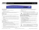
NETVANTA 3448 REAR PANEL LAYOUT
45 V


Find Your Products By Category
- TV and Video
- Communications
- Personal Care
- Portable Media
- Computer Equipment
- Home Audio
- Household Appliance
- Car Audio and Video
- Kitchen Appliance
- Fitness & Sports
- Musical Instruments & Equipment
- Power Tools
- Marine Equipment
- Lawn and Garden
- Automotive
- Photography
- Video Game
- Laundry Appliance
- Outdoor Cooking
- Baby
- Cell Phone
Please Login
