
0
Owner's of the ADTRAN Switch NETVANTA 1200 POE gave it a score of 0 out of 5. Here's how the scores stacked up:


Physical Descriptions NetVanta 1000/1000R Series Hardware Installation Guide
22 Copyright © 2008 ADTRAN, Inc. 61200500L1-34N
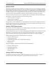
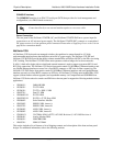
Status LEDs
The status LEDs are located to the lower left of RJ-45 port 1. The WAN LED reflects the status of an
installed NIM. The
DBU LED reflects the status of an installed dial backup interface module (DIM).
The
STAT LED indicates the unit’s status.
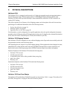
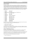
Figure 7. NetVanta 1224R Front Panel Layout
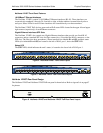
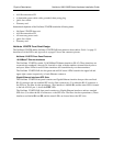
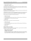
Figure 8. NetVanta 1224R PoE Front Panel Layout
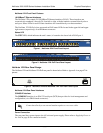
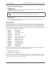
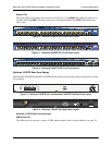
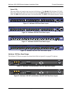
NetVanta 1224R Rear Panel Design
The NetVanta 1224R and NetVanta 1224R PoE rear panel is shown below. Refer to Appendix A on page 67 for
pinouts.
Figure 9. NetVanta 1224R and NetVanta 1224R PoE Rear Panel Layout
NetVanta 1224R Rear Panel Interfaces
NIM Option Slot
The NIM option slot accepts a variety of NIM option modules (refer to Option Modules on page 35).
CONSOLE Interface
The CONSOLE interface is an EIA-232 serial port (DCE) that provides for local management and
configuration (via a DB-9 female connector).
Power Connection
The rear panel has a power input to the AC universal power supply. Please refer to Supplying Power to
the Unit on page 56 for connection details.
Connection directly to an external modem requires a cross-over cable.


Find Your Products By Category
- TV and Video
- Communications
- Personal Care
- Portable Media
- Computer Equipment
- Home Audio
- Household Appliance
- Car Audio and Video
- Kitchen Appliance
- Fitness & Sports
- Musical Instruments & Equipment
- Power Tools
- Marine Equipment
- Lawn and Garden
- Automotive
- Photography
- Video Game
- Laundry Appliance
- Outdoor Cooking
- Baby
- Cell Phone
Please Login
