
0
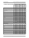
Owner's of the ADTRAN Switch NETVANTA 1200 POE gave it a score of 0 out of 5. Here's how the scores stacked up:


Physical Descriptions NetVanta 1000/1000R Series Hardware Installation Guide
30 Copyright © 2008 ADTRAN, Inc. 61200500L1-34N
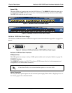
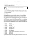
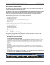
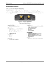
NetVanta 1335 Rear Panel Interfaces
NIM Option Slot
The NIM option slot accepts a variety of NIM option modules (refer to Option Modules on page 35).
CompactFlash
The CompactFlash slot supplies nonvolatile configuration and compressed code storage. The NetVanta
1335 supports only ADTRAN-provided CompactFlash (16 MB to 1 GB) (refer to the part number on
the front cover of this manual).
CONSOLE Interface
The CONSOLE interface is an EIA-232 serial port (DCE) that provides for local management and
configuration (via a DB-9 female connector).
Antenna Connectors
The ANT 1 and ANT 2 ports (NetVanta 1335 WiFi and NetVanta 1335 WiFi PoE only) support two
dual-band antennas for concurrent 802.11a and 802.11b/g connections.
Power Connection
The rear panel has a power input to the AC universal power supply. Please refer to Supplying Power to
the Unit on page 56 for connection details.
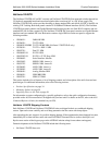
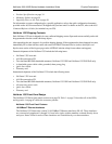
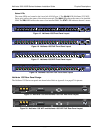
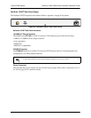
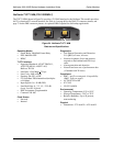
NetVanta 1524ST
The NetVanta 1524ST is a Layer 2 managed switch housed in a 1U-high rack-mountable metal enclosure that
includes a universal AC power supply. The front panel contains 24 10/100/1000BaseT Ethernet interfaces that
are accessed via standard RJ-45 connectors. Four of these twenty-four interfaces can be used in either copper or
fiber mode. Four industry standard SFP slots (supporting industry standard SFP modules) are available for
high-speed uplink or stacking requirements. The switch is managed through an EIA-232
CONSOLE port
(DB-9).
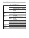
This section includes a list of features, a list of shipping contents, and a description of the unit’s front and rear
panel designs. For additional information, refer to the following sections:
• Product Specifications on page 34
• Mounting Options on page 54
• Supplying Power to the Unit on page 56
For information on switch configuration for a specific application, refer to the quick configuration documents
provided on the AOS Documentation CD shipped with your base unit. For details on the CLI, refer to the AOS
Command Reference Guide (also included on your CD).
Connection directly to an external modem requires a cross-over cable.


Find Your Products By Category
- TV and Video
- Communications
- Personal Care
- Portable Media
- Computer Equipment
- Home Audio
- Household Appliance
- Car Audio and Video
- Kitchen Appliance
- Fitness & Sports
- Musical Instruments & Equipment
- Power Tools
- Marine Equipment
- Lawn and Garden
- Automotive
- Photography
- Video Game
- Laundry Appliance
- Outdoor Cooking
- Baby
- Cell Phone
Please Login
