

0
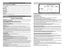
Owner's of the Black & Decker Automobile Battery Charger Black & Decker Automobile Battery Charger gave it a score of 0 out of 5. Here's how the scores stacked up:

FEATURES
• The unit has two voltage rate settings (6v, 12v), controlled by one switch:
a) Use for battery maintenance, charging RVs, speciality vehicles, antique and classic cars, marine deep cycle
batteries, motorcycles, lawn mowers, tractors, ATVs, snowmobiles. personal watercraft and more.
• Maintains battery charge in stored vehicles
• Includes three connector sets:
a) DC accessory plug
b) Battery harness clips
c) Battery ring terminal harness
• Charging indicators:
a) Red – bad connection, battery not able to accept charge, reverse polarity hook-up
b) Blinking Green – connection correct and charging
c) Solid Green – fully charged
• ETL-Listed for safety
• Fully automatic; powers on when needed, powers off when battery is fully-charged or topped-off
• Built-in circuit protection guards against overcharging or short circuit
• Automatically checks for correct polarity (requires a minimum of 2.0 volts battery voltage)
• Convenient, color-coded ring terminals/clamps for easy, correct installation
• Charges with high frequency, pure, DC current
Mounting Instructions:
BM3B battery maintainer is designed to be able to mount to flat surface.
The unit has incorporated two mounting holes at the corners of the unit.
Note: Always disconnect the maintainer at AC power source and at battery terminal when mounting the unit.
To mount the unit:
1. Make sure the surface is flat and free of obstruction so the unit can rest flat on the surface.
2. Make sure the unit is disconnected from both AC power source and the battery.
3. Use 8/32 inches (6.35mm) wood screw to mount the unit through the mounting hole.
4. Do not over tighten the screw, it will damage the housing.
5. Connect the unit to AC power outlet and the unit is ready for use.
WARNING:Do not put the screw through the plastic housing as this will permanently damage the unit and cause
potential electrical hazard.
OPERATING INSTRUCTIONS
Ensure that all installation and operating instructions and safety precautions are understood and carefully followed by
anyone installing or using the charger. Follow the steps outlined in “Important Safety Instructions” at the front of this
manual.
Charging Indicators
Red LED – Bad connection, reverse polarity
connection; check that the RED clamp is connected to + battery terminal.
Blinking Green LED – Connection correct and charging
Solid Green LED – Battery fully charged
When the charger is properly connected, the LED will illuminate, indicating the inside smart circuit is functioning to
judge the battery status. This procedure may take up to 2 minutes if battery voltage is lower than 12.8 volts.
Setting the Voltage
The unit has two voltage rate settings (6v, 12v), controlled by one switch. Set the switch to either 6v or 12v
depending upon the battery you are charging.
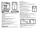
Connecting the Charger with the Terminal Clamps
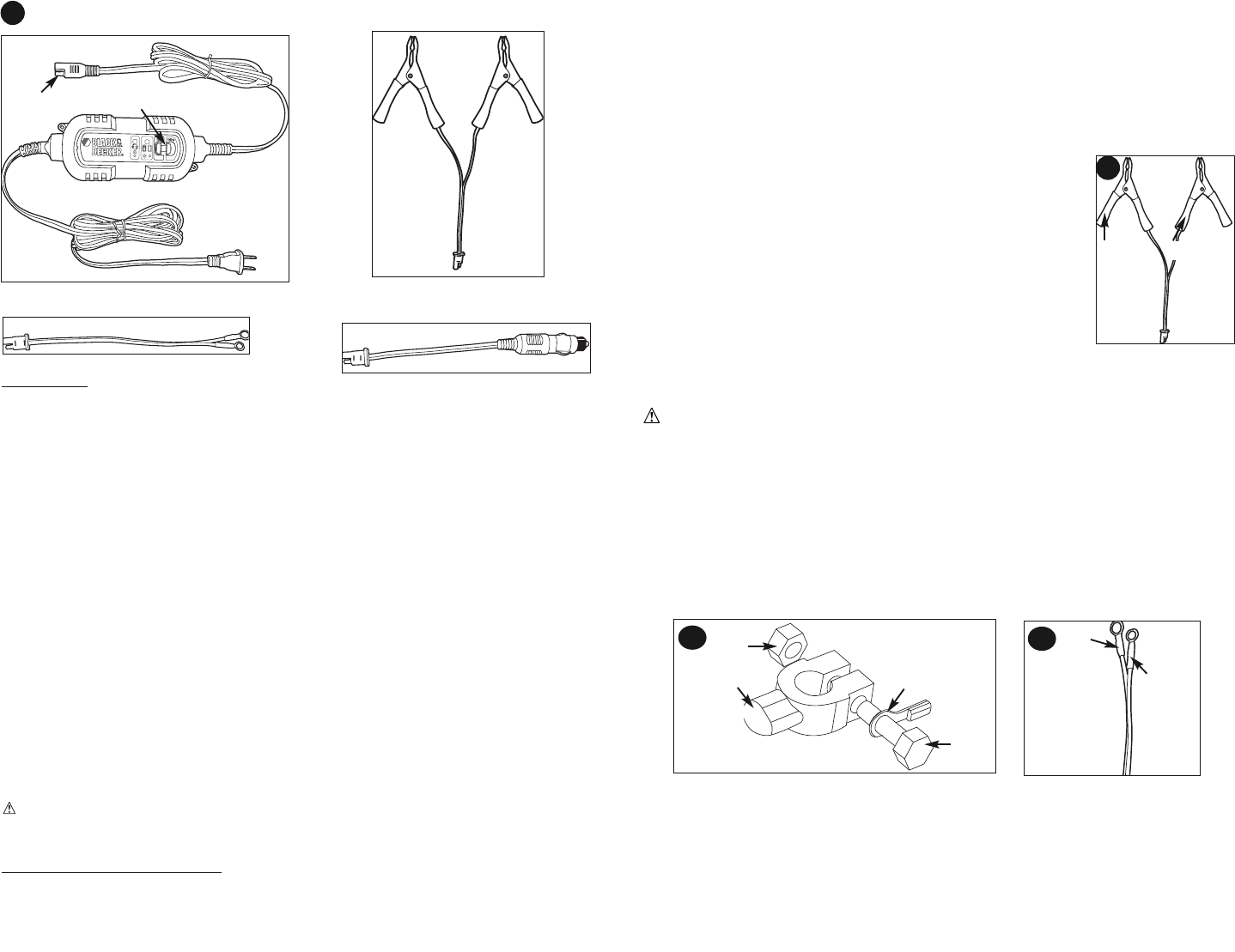
The charger’s output leads have color-coded battery clamps (Figure 2) (RED-POSITIVE and
BLACK-NEGATIVE).
1. Disconnect battery and remove the battery from vehicle.
2. Unplug the battery maintainer AC cord from the AC outlet.
3. Disconnect the battery clamps from the unit at output cord connector.
4. Connect the RED POSITIVE clamp to the POSITIVE post of the battery.
5. Connect the BLACK NEGATIVE clamp to the NEGATIVE post of the battery.
6. Connect the battery clamp connector with the unit connector, as far away from the battery
as possible.
7. Slide the voltage selector to proper setting and plug the AC cord to AC outlet
8. Observe blinking GREEN LED, indicates unit is operating.
9. Monitor the unit periodically.
WARNING: FOLLOW THE STEPS OUTLINED IN "IMPORTANT SAFETY INSTRUCTIONS" AT THE FRONT OF THIS MAN-
UAL AND THE WARNING AT THE BOTTOM OF PAGE 4, "TO REDUCE RISK OF A SPARK NEAR THE BATTERY"
Connecting the Charger with Terminal Rings
The charger’s output leads have crimped, color-coded ring terminals (Figure 3) (RED-POSITIVE and BLACK-NEGATIVE).
These rings connect directly to the corresponding connectors on the battery posts.
1. Remove the nuts from the bolts of the battery post’s connectors.
2. Position the RED terminal on the bolt of the POSITIVE battery post connector.
3. Position the BLACK terminal on the NEGATIVE post connector; then replace the nuts.
4. If there is any problem connecting the output leads, check with a reputable auto supply store or contact the
Customer Service Department toll-free at (800) 544-6986 for assistance in finding an appropriate connection device
for your particular application.
Charging With Ring Terminals
1. Disconnect AC power cord from AC power outlet
2. Disconnect battery terminal clamps and DC accessory plug from the maintainer output cable, at connector
3. With the ring terminals connected (fig. 3a) and with ring terminal connector held as far away from battery, connect to the
maintainer output cord. If the maintainer red LED is lit, check ring terminal connections at battery.
4. Slide the voltage selector switch to 6V or 12V
5. Connect AC power
6. The unit should be working with blinking green LED, indicating the battery is being charged.
RED
BLACK
2
6 7
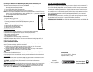
BATTERY TERMINAL RINGS
DC ACCESSORY PLUG
6V/12V BATTERY MAINTAINER
BATTERY TERMINAL CLAMPS
1
110/120 VOLT
AC PLUG END
6 VOLT / 12 VOLT SWITCH
RED
BLACK
CONNECTOR
NUT
BOLT
TERMINAL RINGS
3a
3b
Charger Connector


Find Your Products By Category
- TV and Video
- Communications
- Personal Care
- Portable Media
- Computer Equipment
- Home Audio
- Household Appliance
- Car Audio and Video
- Kitchen Appliance
- Fitness & Sports
- Musical Instruments & Equipment
- Power Tools
- Marine Equipment
- Lawn and Garden
- Automotive
- Photography
- Video Game
- Laundry Appliance
- Outdoor Cooking
- Baby
- Cell Phone
Please Login
