
0
Owner's of the Blue Sea Systems Marine RADAR Blue Sea Systems Marine RADAR gave it a score of 0 out of 5. Here's how the scores stacked up:
1. Disconnect all AC and DC power
Before starting, disconnect the main positive cable from all batteries to
eliminate the possibility of a short circuit while installing the distribution
panel. Also disconnect the AC shore power cord from the boat to
eliminate the possibility of electrocution from AC wiring in the proximity
of the DC distribution panel.
2. Select mounting location and cut opening
Select a mounting location which is not in an area where fl ammable
vapors from propane, gasoline or lead acid batteries accumulate. This
panel is not ignition protected and may ignite such vapors.
Using the panel template provided, make a cut out in the mounting
surface where the distribution panel is to be mounted. Do not yet
fasten the panel to the mounting surface.
3. Select positive feed wire
Determine the positive feed (red) wire size by calculating the total
amperage of the circuits that will be routed through the panel. Blue Sea
Systems’ water resistant electrical panels are rated at 45 amp total
capacity. The positive feed wire must be sized for 3% voltage drop at
the 45 amp panel rating or the maximum amperage that will be routed
through the panel in any particular installation, whichever is less. It is
recommended that the positive feed wire be sized for the full panel
capacity, which, in most cases, will require at least 8 AWG wire,
assuming a 10 foot wire run between the panel and the batteries in
12 volt systems. Refer to the Wire Sizing Chart for other situations.
Remember that the length of the circuit is the total of the positive wire
from the power source and the negative wire back to the DC Negative
Bus. Be certain that there is a fuse or circuit breaker of the correct size
protecting the positive feed wire.
4. Install LED negative feed wire
Use a 16 AWG wire to connect the LED negative feed (yellow) wire to
the DC Negative Bus.
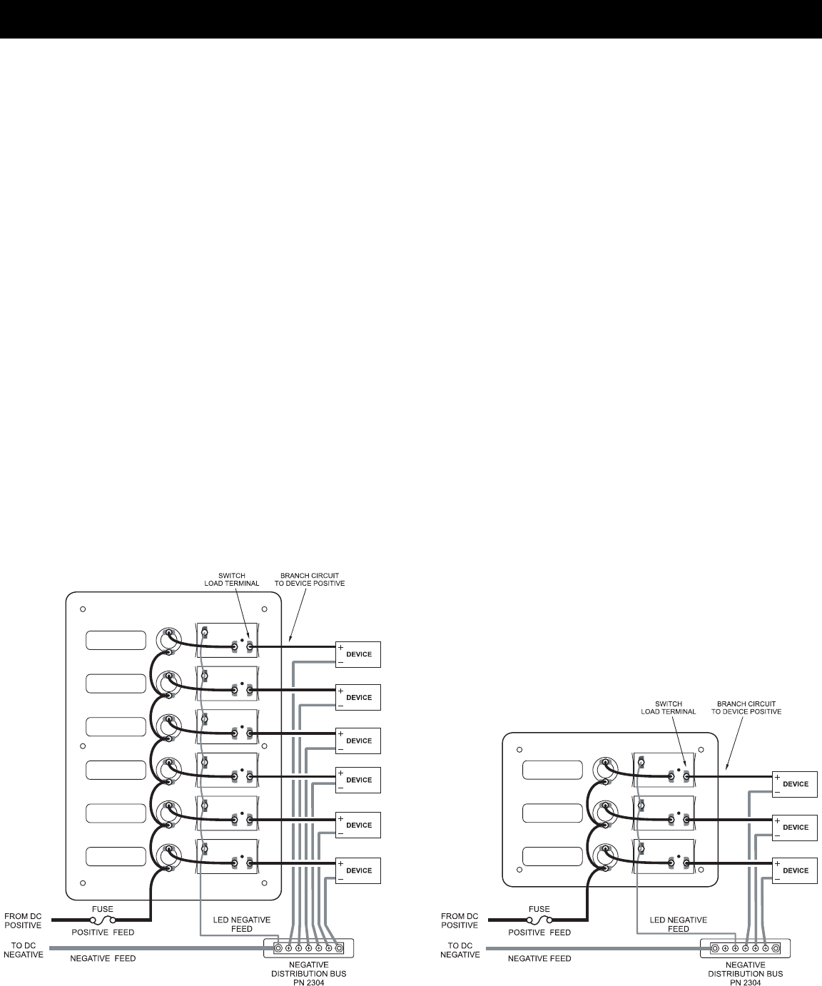
5. Install branch circuit wires
Determine the proper wire size for each branch circuit using the
guidelines in step 3. Verify that the standard 15 amp fuses installed in
the panel are appropriate for each branch circuit. Remove and
replace if necessary. Connect the positive (red) branch circuit wires to
the load terminals of each switch. Connect each negative (black)
branch circuit wire to a DC Negative Bus such as Blue Sea Systems’
MiniBus PN 2304.
6. Apply branch circuit labels
For each branch circuit, select a label from the 30 basic labels
provided, and apply it to the recessed area on the front of the panel.
If the appropriate labels are not found, the Extended Label Set of 120
labels may be ordered from your marine supplier (PN 8039). Individual
labels are also available from Blue Sea Systems, and may be ordered
using the provided Label Order Form.
7. Mount Panel with water resistant gasket
A gasket has been included for sealing the panel against the mounting
surface. The gasket will easily stretch around the panel when applied
from the front. Place the gasket between the panel and the mounting
surface. Make sure all surfaces are clean and free from debris. Using
the panel mounting screws supplied with the panel, screw down the
panel to the mounting surface.
8. Testing
Reconnect the main positive cable to the battery terminals and turn the
main switch on to supply power to the panel. Turn on all branch circuits
and test the voltage at the panel. Compare this voltage to the battery
terminal voltage to determine that the voltage drop is within 3%. With
all branch circuits still on, test the voltage at one device on each circuit
to determine that there is a 3% or 10% drop as is appropriate.
Note
This Blue Sea Systems electrical distribution panel is furnished with 15
amp AGC (fast acting) glass fuses. This rating was selected to minimize
the need for removing the fuse and reinstalling different size fuses. 15
amp fuses will satisfy the vast majority of marine circuit protection
situations.
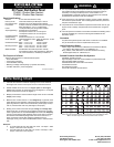
Applicable Standards
• American Boat and Yacht Council (ABYC) Standards and
Recommended Practices for Small Craft sections: E-1, E-3, E-9.
• United States Coast Guard 33 CFR Sub Part 1, Electrical Systems.
Installation
Wiring Diagram
DC Water Resistant Power Distribution Panel
PN 8053
Wiring Diagram
DC Water Resistant Power Distribution Panel
PN 8054


Find Your Products By Category
- TV and Video
- Communications
- Personal Care
- Portable Media
- Computer Equipment
- Home Audio
- Household Appliance
- Car Audio and Video
- Kitchen Appliance
- Fitness & Sports
- Musical Instruments & Equipment
- Power Tools
- Marine Equipment
- Lawn and Garden
- Automotive
- Photography
- Video Game
- Laundry Appliance
- Outdoor Cooking
- Baby
- Cell Phone
Please Login
