
0
Owner's of the Bogen Microphone Bogen Communications Microphone gave it a score of 0 out of 5. Here's how the scores stacked up:

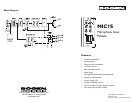

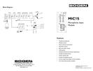
Gain
Provides control over the level of input signal that can be applied to the
internal signal buses of the main unit. Allows a way to balance the input lev-
els of various devices so that the main unit controls can be set to relative-
ly uniform or optimum levels.
Bass & Treble (Treb)
Provides separate controls for Bass and Treble cut and boost.The Bass control
affects frequencies below 100 Hz and Treble affects frequencies above 8 kHz.
Clockwise rotation provides boost, counterclockwise rotation provides cut.
Center position provides no affect.
Gate - Threshold (Thresh)
Controls the minimum necessary input signal level to turn the module’s out-
put on and apply signal to the main unit's buses.Clockwise rotation increas-
es the necessary signal level required to produce output and mute lower
priority modules.
Gate - Duration (Dur)
Controls the amount of time the output and mute signal of the module
remains applied to the main unit’s buses after the input signal falls below the
required minimum signal level (set by the threshold control).
Limiter (Limit)
Sets the signal level threshold at which the module will begin to limit the
level of its output signal. Clockwise rotation will allow more output signal
before limiting, counterclockwise rotation will allow less.The limiter moni-
tors the module’s output signal level,so increasing Gain will affect when lim-
iting takes place.An LED indicates when the Limiter is active.
Connections
Uses screw terminal block to make connections to the module’s input.The
input is low-impedance, transformer-balanced for excellent noise and ground
loop immunity.
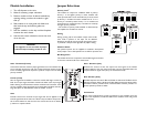
Jumper Selections
Priority Level
*
This module can respond to 4 different levels of priority.
Priority 1 is the highest priority. It mutes modules with
lower priorities and is never muted.Priority 2 can be muted
by Priority 1 modules and mutes modules set for 3 or 4.
Priority 3 is muted by either Priority 1 or 2 modules and
mutes Priority 4 modules. Priority 4 modules are muted by
all higher priority modules.
* The number of priority levels available is determined by
the amplifier the modules are used in.
Bus Assignment
This module can be set to operate so that the MIC signal can be sent
to the main unit’s A bus, B bus, or both buses.
Phantom Power
24V phantom power can be supplied to condenser microphones
when jumper is set to ON position. Set to OFF for dynamic mics.
Module Installation
1. Turn off all power to the unit.
2. Make all necessary jumper selections.
3. Position module in front of desired module bay
opening, making sure that the module is right-
side up.
4. Slide module on to card guide rails. Make sure
that both the top and bottom guides are
engaged.
5. Push the module in to the bay until the faceplate
contacts the unit’s chassis.
6. Use the two screws included to secure the mod-
ule to the unit.
WARNING:
Turn off power to unit and make all jumper
selections before installing module in unit.
Gating
Gating (turning off) of the modules output when insuffi-
cient audio is present at the input can be disabled.
Detection of audio for the purpose of muting lower prior-
ity modules is always active regardless of jumper setting.


Find Your Products By Category
- TV and Video
- Communications
- Personal Care
- Portable Media
- Computer Equipment
- Home Audio
- Household Appliance
- Car Audio and Video
- Kitchen Appliance
- Fitness & Sports
- Musical Instruments & Equipment
- Power Tools
- Marine Equipment
- Lawn and Garden
- Automotive
- Photography
- Video Game
- Laundry Appliance
- Outdoor Cooking
- Baby
- Cell Phone
Please Login
