
0
Owner's of the Channel Plus Telephone DMT-16 gave it a score of 0 out of 5. Here's how the scores stacked up:
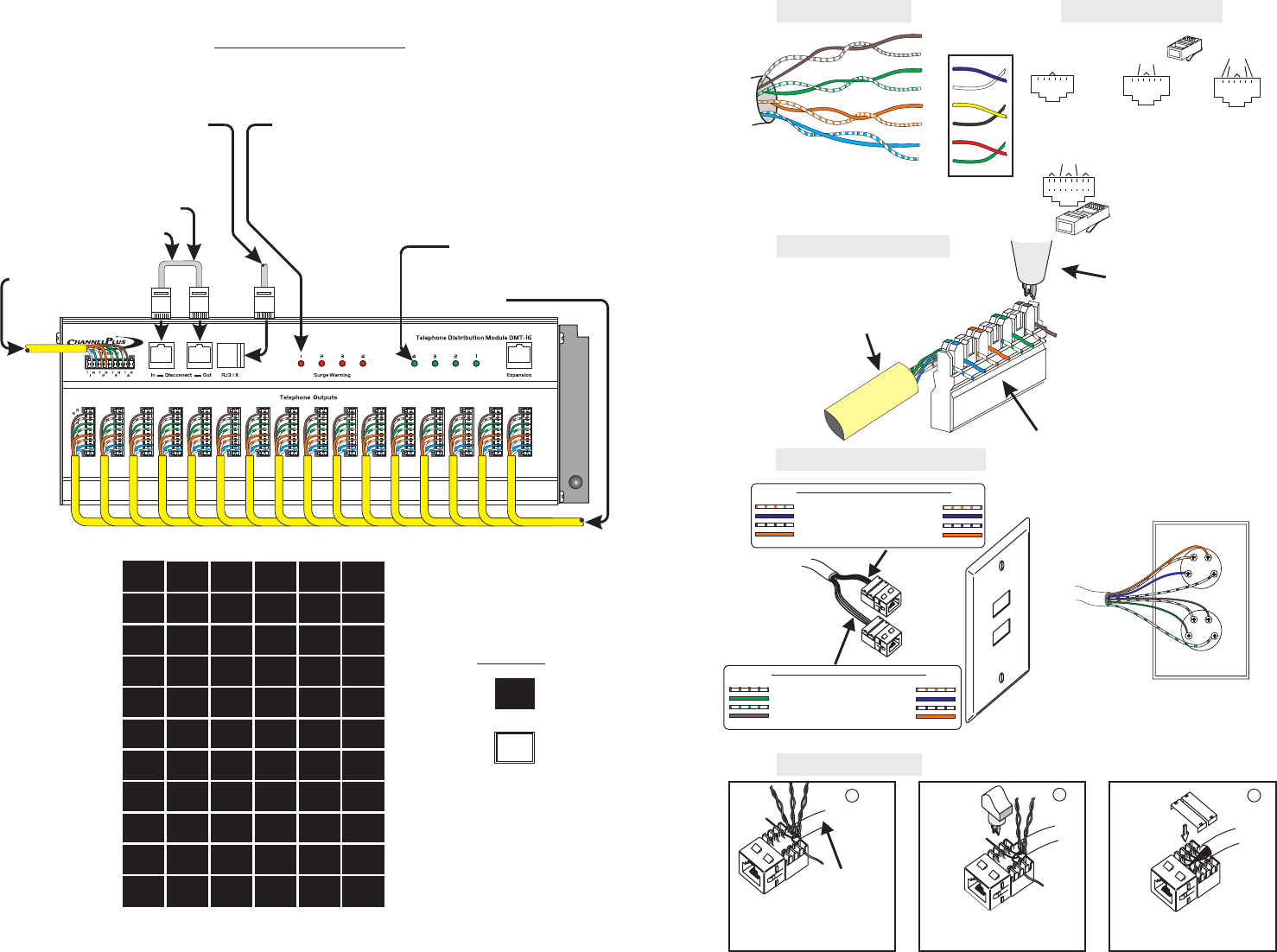
Expansion Jumper
(included)
Install this jumperfor normal
operation. Remove to
disconnect telephone
servicefrom the system.
Each line is individually surge protected to 50
Joules and 4000 Amps. Some surges contain
sufficient energy that although your system
has been protected, the surge circuit will be
unable to provide additional protection. When
this happens, the red light for that line will turn
on and the module needs to be returned for
service.
From telephone
company4 Lines
4 Lines to 16
telephone wall
plates.
Security system connection
(RJ-31X)
Telephone Distribution Module DMT-16
Active Line Indicators
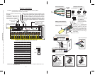
Typical Installation
Family
Room
Guest
House 2
Basement
Bathroom
Bedroom
4
Bathroom
1
Bathroom
3
Bedroom
Bedroom
1
Bedroom
2
Bedroom
3
Bathroom
2
Back
Door
Master
Suite 2
Dining
Room
Game
Room
Garage
Garage
2
Guest
House 1
Family
Room
FAX
FAX
2
Fitness
Center
Front
Door
Guest
House
Bedroom
6
Bedroom
7
Bedroom
5
Den
Den
2
Children’s
Room
Children’s
Room 1
Children’s
Room 2
Children’s
Room 3
Children’s
Room 4
Satellite
Satellite
1
Satellite
2
Satellite
3
Satellite
4
Patio
Play
Room
Pool
House
PVR
PVR
1
Master
Suite 3
Master
Suite 4
Media
Center
Media
Center 1
Media
Center 2
Modem
2
Modem
Office
Office
1
Office
2
Office
3
Guest
Room
Guest
Room 2
Hall
Hall
2
Kitchen
Laundry
Room
Living
Room
Master
Suite
Master
Suite 1
Guest
Room 1
Bat
Phone
Label Card: Separate and slide labels into extrusion, or flip the label over for a
blank surface.
Front
Rear
Example
2
Included: (1) Expansion Jumper 24”. (2) Flat Surface Mounting Ears.
(1) Disconnect Jumper (66) Labels
Line Ringing
®
3
Black
Green
Yellow
Red
Pairs 1 & 2
Pairs 3 & 4
Option: old style wall plate
Pairs 3 & 4
Pairs 1 & 2
RJ-14
Voice Grade Jacks
Cable Color Pin # Connector Color
Pin 1
White/Orange Pin 2 White/Orange
Blue Pin 3 Blue
White/Blue Pin 4 White/Blue
Orange Pin 5 Orange
Pin 6
N/C
N/C
Cable Color Pin # Connector Color
Pin 1
White/Brown Pin 2 White/Orange
Green Pin 3 Blue
White/Green Pin 4 White/Blue
Brown Pin 5 Orange
Pin 6
N/C
N/C
8 position connectors
TRTRT TRR
12345 768
PR2
PR1
PR3
PR4
RJ-11
Single line
telephones,
RJ-14
Dual line
telephones &
RJ-25
Rare
3 line KSU
RJ-45 (wired to TIA
T568A standard)
Ethernet (both 10BaseT
and 100BaseT)
Structured wiring of
phones and data lines
Follow color code forT568A jacks.
Position first pair to channel closest
to end of jack. (Do not untwist
conductor pairs more than 0.5"
from the termination point.)
Keep sheath
close to jack.
1
Using a 110 punch-down tool,
push wires into channels
Repeat for subsequent pairs.
and
trim.
110 punch-
down tool
110 punch-
down tool
2
When all conductor pairs are
terminated, snap on strain relief
caps.
3
Wiring a Cat-5 jack
Keep sheath close to connector
Untwist .5” max.
110 punch down tool
Note order of colors
Wiring a telephone wall plate
Black
Green
Yellow
Red
Wiring a 110 connector
green
black
white
red
yellow
blue
TIP
TIP
TIP
TIP
RING
RING
RING
RING
Cat5
4 pair UTP
blue/white
blue
orange/white
orange
green/white
green
brown/white
brown
pair 1
pair 2
pair 3
pair 4
pair 1
pair 2
pair 3
Solid Color
Twisted-Pair
Wire
Modular connectors
6 position connectors
T
T
T
R
R
R
T
T
T
R
RR
1
1
1
2
2
2
3
3
3
4
4
4
5
5
5
6
6
6
PR2
PR1
PR3
PR2
PR1
PR1
Wire Color Codes
The 110 is a sophisticated
insulation displacement
connection system. To push the
wires between the contact blades,
use only a 110 punch down tool.
Using a screwdriver may not seat
the wire properly and can damage
thecontacts.
PRINTER'S INSTRUCTIONS:
MANUAL,DMT-16 - LINEAR P/N:600-230 C - INK:PROCESS COLOR - MATERIAL:20 LB.MEAD BOND - SIZE:FLAT 11.000" X 8.500" FINISHED 5.500" X 8.500" - FOLDING: 1-FOLDVERTICAL - SCALE:1-1 - SIDE 2 OF 2


Find Your Products By Category
- TV and Video
- Communications
- Personal Care
- Portable Media
- Computer Equipment
- Home Audio
- Household Appliance
- Car Audio and Video
- Kitchen Appliance
- Fitness & Sports
- Musical Instruments & Equipment
- Power Tools
- Marine Equipment
- Lawn and Garden
- Automotive
- Photography
- Video Game
- Laundry Appliance
- Outdoor Cooking
- Baby
- Cell Phone
Please Login
