
0
Owner's of the Digital Antenna Musical Instrument Amplifier POWERMAX gave it a score of 0 out of 5. Here's how the scores stacked up:

12
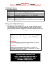
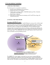
6. RV Installation
Review pre-installation considerations and determine site installation plan.
1. Install supplied outside antenna (PN 288-PW) to vertical surface or pole with
supplied hardware. Outside antenna must be mounted in a vertical position.
Mount the outside antenna clear of metal objects and obstructions and as high as
possible but take care not to exceed height of other roof mounted items such as
A/C. The base of the antenna only can be attached or next to metal. The white
fiberglass portion should not be next to metal. Antennas must be separated by a
structure and a 40’ or greater distance with as much vertical separation as
possible. Vertical separation is better than horizontal.
WARNING! Only Digital Antenna authorized products may be used with the
4KSBR-50U system. Using unauthorized equipment with the 4KSBR-50U
system will harm the system, can be detected and voids the warranty.
2. On supplied 50’ cable (PN 340-50NM) (or optional 25’ extension cable or 75’ or
100’ replacement PowerMax
TM
cable) attach N male connector to N female
connector on outside antenna. Secure cable to the side of the building with
appropriate fasteners (not supplied). Route cable according to site installation plan
to the DA4000SBR unit.
3. Attach mini-UHF male connector at the end of the supplied 50’ cable to
DA4000SBR unit on the port labeled outside antenna. Attach the 6’ cable
attached to the inside antenna and stand to the port labeled inside antenna. The
inside antenna must be operated in a vertical position. DO NOT turn the
repeater on until antennas and cables are securely attached.
4. The DA4000SBR unit has four mounting holes that can be fastened to a secure
surface. (fastening hardware not included)
5. When using 110VAC - Plug 100-240VAC power supply to the DA4000SBR unit.
Plug the other end into standard 110VAC receptacle.
When using 12VDC – Plug the 12 VDC to 5 VDC power cable (PN DP515) into
the DA4000SBR unit. Plug the other end into a 12VDC cigarette style power
source.
The 12 VDC power supply, PN DP515, has a micro-processor controller to turn
the repeater off if not properly installed. If a red flashing light appears on the
power supply, relocate the inside and outside antennas until the power supply has
a constant green light. The power supply can be reset by unplugging the cigarette
adapter from the power source.
WARNING!
To have DC power hardwired consult a professional electronic technician.
6. Turn the power switch to ON. If the light on the DA4000SBR unit is green and
the coverage area is greater than 1-2’ then the 4KSBR-50U system is operating.
Test the amplifier/repeater system by making a cell call and verifying that the
indicator light does not turn red. If the light on the DA4000SBR unit is red
immediately turn OFF the DA4000SBR unit and refer to the Amplifier/Repeater
status section.


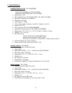
Find Your Products By Category
- TV and Video
- Communications
- Personal Care
- Portable Media
- Computer Equipment
- Home Audio
- Household Appliance
- Car Audio and Video
- Kitchen Appliance
- Fitness & Sports
- Musical Instruments & Equipment
- Power Tools
- Marine Equipment
- Lawn and Garden
- Automotive
- Photography
- Video Game
- Laundry Appliance
- Outdoor Cooking
- Baby
- Cell Phone
Please Login
