

0
Owner's of the Furuno Musical Instrument Wind Angle, Course Pilot, Rudder Instrument gave it a score of 0 out of 5. Here's how the scores stacked up:


iii
TABLE OF CONTENTS
FOREWORD ............................................................................................... iv
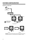
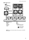
SYSTEM CONFIGURATION ..................................................................... vi
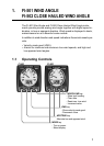
1. FI-501 WIND ANGLE, FI-502 CLOSE HAULED WIND ANGLE............. 1
1.1 Operating Controls ............................................................................................... 1
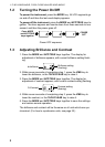
1.2 Turning the Power On/Off .................................................................................... 2
1.3 Adjusting Brilliance and Contrast ......................................................................... 2
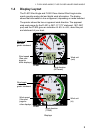
1.4 Display Layout...................................................................................................... 3
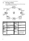
1.5 Selecting a Display............................................................................................... 4
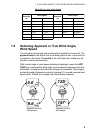
1.6 Selecting Apparent or True Wind Angle, Wind Speed ......................................... 5
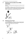
1.7 Displaying Velocity Made Good (VMG) Information............................................. 6
1.8 Displaying Tack Angle.......................................................................................... 6
1.9 Alarms .................................................................................................................. 7
2. FI-505 COURSE PILOT ........................................................................... 9
2.1 Operating Controls ............................................................................................... 9
2.2 Turning the Power On/Off .................................................................................. 10
2.3 Adjusting Brilliance and Contrast ....................................................................... 10
2.4 Selecting a Display............................................................................................. 11
2.5 Unlocked and Locked Heading Modes............................................................... 12
2.6 Resetting Average Heading Indication ............................................................... 12
3. FI-506 RUDDER..................................................................................... 13
3.1 Operating Controls ............................................................................................. 13
3.2 Turning the Power On/Off .................................................................................. 14
3.3 Adjusting Display Brilliance ................................................................................ 14
3.4 Calibrating Rudder Angle ................................................................................... 14
4. MAINTENANCE,TROUBLESHOOTING ............................................... 15
4.1 Preventive Maintenance..................................................................................... 15
4.2 Troubleshooting.................................................................................................. 16
5. INSTALLATION ..................................................................................... 17
5.1 Equipment Lists.................................................................................................. 17
5.2 Mounting............................................................................................................. 19
5.3 Wiring ................................................................................................................. 23
5.4 Setting Up........................................................................................................... 29
SPECIFICATIONS ................................................................................. SP-1
PACKING LIST ........................................................................................ A-1
OUTLINE DRAWINGS............................................................................. D-1
INTERCONNECTION DIAGRAM ............................................................ S-1


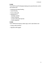
Find Your Products By Category
- TV and Video
- Communications
- Personal Care
- Portable Media
- Computer Equipment
- Home Audio
- Household Appliance
- Car Audio and Video
- Kitchen Appliance
- Fitness & Sports
- Musical Instruments & Equipment
- Power Tools
- Marine Equipment
- Lawn and Garden
- Automotive
- Photography
- Video Game
- Laundry Appliance
- Outdoor Cooking
- Baby
- Cell Phone
Please Login
