

0
Owner's of the Viking Electronics Video Gaming Accessories Viking Electronics Video Gaming Accessories gave it a score of 0 out of 5. Here's how the scores stacked up:
Due to the dynamic nature of the product design, the information contained in this document is subject to change without notice. Viking Electronics, and its affiliates and/or
subsidiaries assume no responsibility for errors and omissions contained in this information. Revisions of this document or new editions of it may be issued to incorporate
such changes.
Fax Back Doc 813
ZF300160 Rev D
Printed in the U.S.A.
P
P
r
r
o
o
d
d
u
u
c
c
t
t
S
S
u
u
p
p
p
p
o
o
r
r
t
t
L
L
i
i
n
n
e
e
.
.
.
.
.
.
7
7
1
1
5
5
.
.
3
3
8
8
6
6
.
.
8
8
6
6
6
6
6
6
F
F
a
a
x
x
B
B
a
a
c
c
k
k
L
L
i
i
n
n
e
e
.
.
.
.
.
.
7
7
1
1
5
5
.
.
3
3
8
8
6
6
.
.
4
4
3
3
4
4
5
5
I
I
n
n
s
s
t
t
a
a
l
l
l
l
a
a
t
t
i
i
o
o
n
n
Important: Electronics componants are sensitive to stat-
ic electricity. Personnel and the work area should be
grounded before handling.
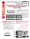
B. DVA-500A and DVA-1003B Memory Expansion
1. Disconnect the power and telecom connections to the
DVA-500A or DVA-1003B.
2. Remove the (4) screws on the bottom of the unit, then
remove the cover.
3. Insert the ERAM chip(s) carefully into the appropriate
socket(s) with the indents facing in the direction shown.
4. Replace the cover and screws of the DVA-500A or
DVA-1003B.
Important: Electronics componants are sensitive to static electricity. Personnel and the work area should be ground-
ed before handling.
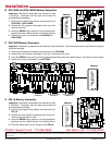
C. DVA-3003 Memory Expansion
1. Disconnect the power and telecom connections to the DVA-3003.
2. Remove the (4) screws on the bottom of the unit, thenremove the cover.
3. Insert the ERAM chip(s) carefully into the appropriate socket(s) with the indents facing in the direction shown below.
4. Replace the cover and screws of the DVA-3003.
Important: Electronics componants are sensitive to stat-
ic electricity. Personnel and the work area should be
grounded before handling.
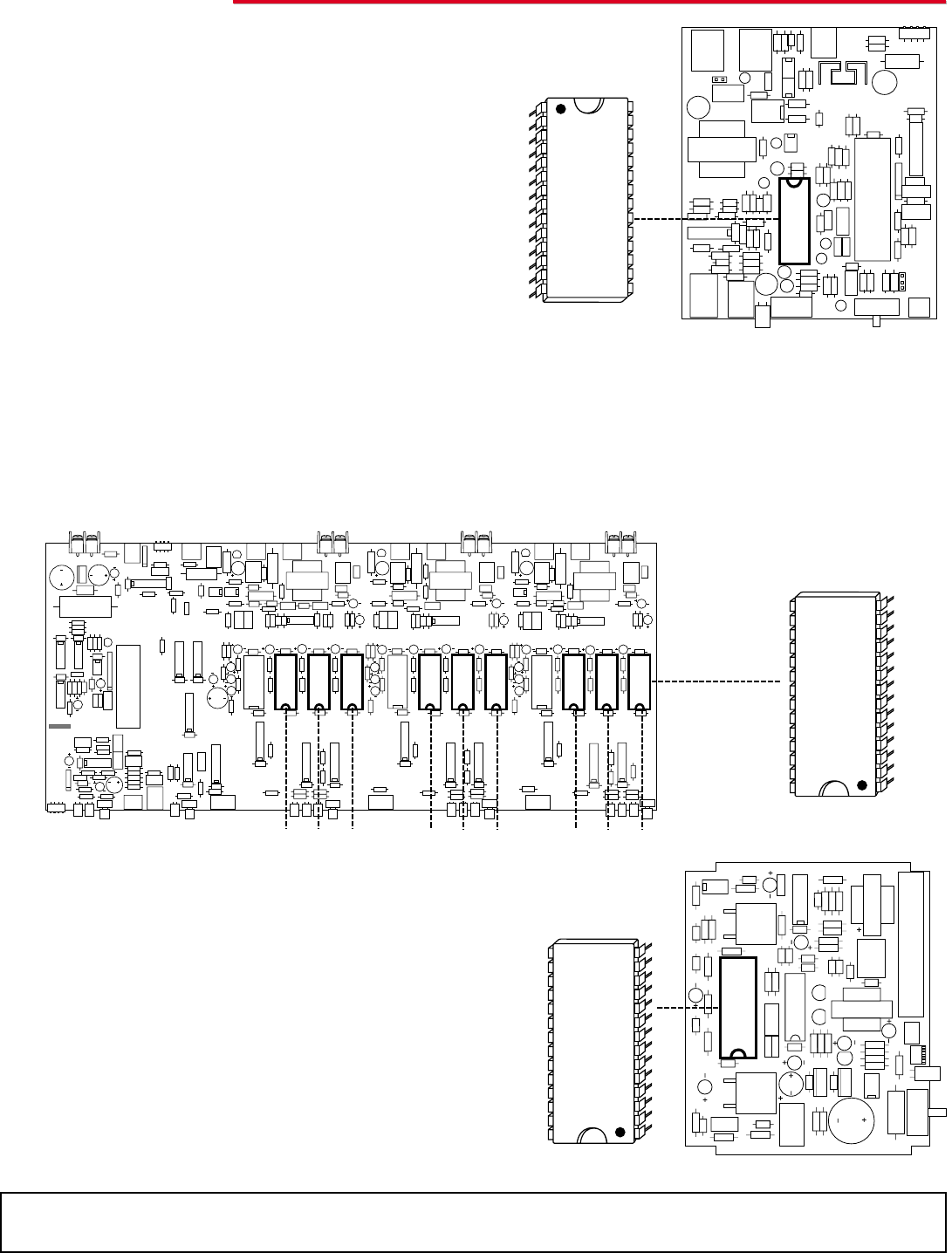
D. FBI-1A Memory Expansion
1. Disconnect the power and telecom connections to the
FBI-1A.
2. Remove the circuit board by spreading the aluminum
housing until the board is free.
3. Insert the ERAM chip(s) carefully into the appropriate
socket(s) with the indents facing in the direction shown.
4. Place the board back into the chassis of the FBI-1A.
258511 REV B
LED
LED
21
LED LED
3
LED LED LED
33
333
VIKING ELECTRONICS
ERAM-60 REV B
ERAM-60
VIKING ELECTRONICS
ERAM-60 REV B
ERAM-60
VIKING ELECTRONICS
ERAM-60 REV B
ERAM-60
Kit 1 Kit 2 Kit 3
Channel 1
Kit 1 Kit 2 Kit 3
Channel 2
Kit 1 Kit 2 Kit 3
Channel 3


Find Your Products By Category
- TV and Video
- Communications
- Personal Care
- Portable Media
- Computer Equipment
- Home Audio
- Household Appliance
- Car Audio and Video
- Kitchen Appliance
- Fitness & Sports
- Musical Instruments & Equipment
- Power Tools
- Marine Equipment
- Lawn and Garden
- Automotive
- Photography
- Video Game
- Laundry Appliance
- Outdoor Cooking
- Baby
- Cell Phone
Please Login
