

0
Owner's of the AudioSource Speaker System Impedance Matching Volume Control gave it a score of 0 out of 5. Here's how the scores stacked up:
Note: UL rated CL3 speaker wire is recommended when
running wire inside your walls. In many localities it may be
required by code. When installing your speaker wire, avoid
running the speaker wire parallel to any 120V power lines to
avoid picking up hum and interference from the power service.
If the speaker wire needs to cross a 120V power line at a
right angle this is acceptable and will not create a problem.
If you are uncomfortable with running the speaker wire yourself
in existing construction, it is recommended that you retain a
qualified custom home installation specialist or electrician.
Congratulations on your purchase of the AudioSource
AE100VC Impedance Matching Volume Control. This
product will allow you to install stereo speakers
throughout your home and control them, without
overloading your receiver or amplifier.
Please read this Manual to ensure the proper
installation and best performance of your AE100VC
Impedance Matching Volume Control.
AE100VC
Impedance Matching Volume Control
Function of the AE100VC
The AE100VC features high quality audio transformers,
removable solderless connection terminals and a
computer grade double-sided glass-epoxy printed circuit
board. An impedance matching switch multiplies the
impedance the amplifier “sees” by two, four or eight
times, allowing parallel connection of multiple AE100VCs
without damaging the amplifier. Twelve knob positions
provide a maximum of 39dB of attenuation. The AE100VC
package includes a metal mounting bracket, and three
sets of color matched knobs, plastic inserts, and screws.
(White, Bone and Ivory)
Installation and Connection Procedures
Carefully choose the location for mounting the AE100VC.
For safety, and to avoid picking up hum and noise from
your electrical system, never put the AE100VC into the
same box as a light switch or dimmer.
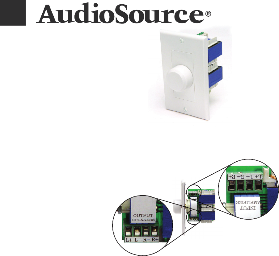
Polarity (+/-) for the input and output speaker terminals
is clearly marked on the rear of the AE100VC. Speaker
wire is coded to identify each conductor as either
positive (+) or negative (-). This may be by color coding,
or one conductor may have a printed marking or a rib
along one edge that you will not find on the other. Identify
which type of polarity coding that your wire is using and
which conductor is positive (+) or negative (-).
1. Route the speaker cables from the amplifier and
each speaker pair to the location of the AE100VC paying
close attention to which wires connect to the speakers and
which connect to the amplifier. Mark them if needed.
2. Strip 3/8” insulation from the end of the cables and
twist the exposed ends to avoid fraying.
3. Remove the speaker and amplifier connectors from the
terminals marked Input and Output. Insert the wires into
their respective connector positions and tighten the screws.
4. Plug the connectors onto the circuit board terminals
being careful to observe markings for Input and Output.
If you are using a metal J-Box, insure that none of the
speaker wiring can short to the metal of the box.
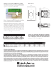
Recommended Speaker Wire Gauges
The resistance of the speaker wire in your installation
can cause your speakers to perform at less than their
optimum quality level. Excess resistance caused by
using an undersized speaker wire can result in loss of
detail and definition in the bass region of your audio
program, as well as loss of dynamic range. Over extremely
long wire runs you may even experience a loss of high
frequency content in the audio signal.
To prevent sonic degradation in your speaker installation,
total speaker wire resistance should be kept below
0.5 ohms. The following table lists recommended speaker
wire gauge versus wire run length.
50’ or less - 16 Gauge 2-Cond. CL3 Rated
50’ - 150’ - 12 Gauge 2-Cond. CL3 Rated
150’ - 200’ - 10 Gauge 2-Cond. CL3 Rated


Find Your Products By Category
- TV and Video
- Communications
- Personal Care
- Portable Media
- Computer Equipment
- Home Audio
- Household Appliance
- Car Audio and Video
- Kitchen Appliance
- Fitness & Sports
- Musical Instruments & Equipment
- Power Tools
- Marine Equipment
- Lawn and Garden
- Automotive
- Photography
- Video Game
- Laundry Appliance
- Outdoor Cooking
- Baby
- Cell Phone
Please Login
