
0
Owner's of the AudioSource Stereo Amplifier 12-Channel Power Amplifier gave it a score of 0 out of 5. Here's how the scores stacked up:
(3)
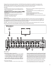
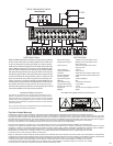
REAR PANEL:
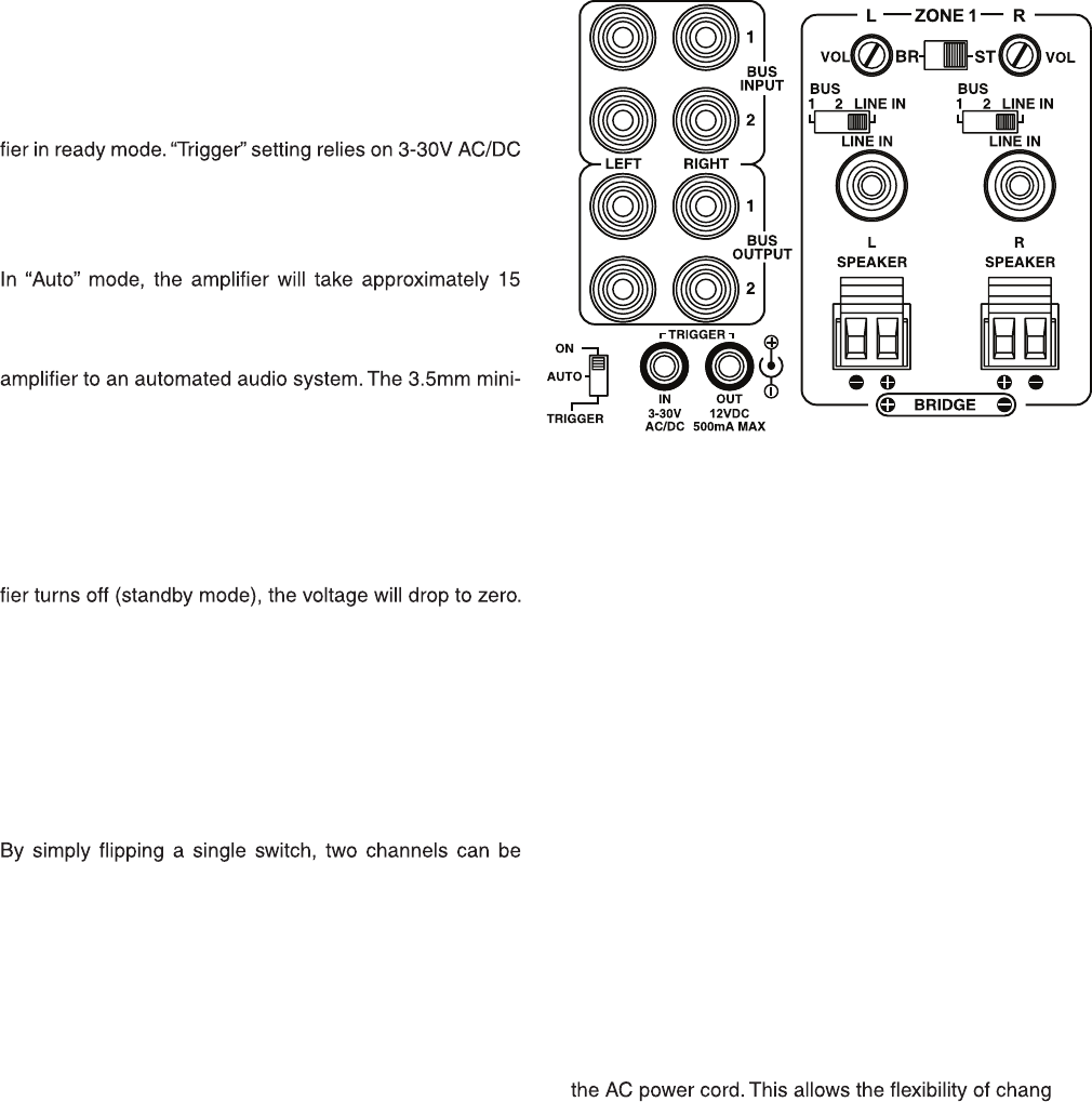
3. BUS Line Inputs / Outputs
The AMP1200 has t
wo common or BUS inputs that
recei
ves audio signals from standard line-level audio
sources and sends them to a
ny or all channels. The BUS
line outputs are direct
feed-through to allow the BUS
inputs to be fed to other amplifiers. Be sure to use high
quality RCA ca
bles that feature low impedance, shielding
and high quality connector
s.
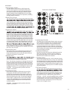
4. Remote Turn-On Switch
This
switch selects the turn-on stimuli that will put the ampli -
voltage going into the trigger input to activate the amplifier.
“Auto” setting senses a signal on the RCA line-level inputs
and
automatically puts the amp in ready mode. “On” setting
puts the amp constantly in ready mode so that it can be
controlled
by the master power switch on the front panel.
minutes to return from ready to standby mode.
5. Trigger Input / Output
The
trigger input is a handy feature when connecting the
plug jack will accept a 3-30V AC/DC output from another
device, or from a separate power supply. When the trigger
input
is energized, the amp turns from standby to ON mode.
When
using the AMP1200 with a receiver without a trigger
output,
the voltage can come from a 12V wall wart (3.5mm
tip-positive connector) plugged into the receiver’s switched
outlet
and the trigger input. The AMP1200 can also provide
an
output trigger voltage (12DC @500mA max.) to turn on
and
off other devices in the audio system. When the ampli -
Note: Remember there is a delay of approximately 15
mi
nutes before the amplifier goes to standby when using
the
“Auto” turn-on mode.
6. Channel Gain Control
Each channel has its
own independent level adjustment.
This all
ows the output level of each speaker to be per -
fectly matched to its area. It can also be used to limit the
maxi
mum audio level in a certain area.
7. Bridging Switch
combined to increase the total power output. This is helpful
when
extra power is needed in certain areas.
Note:
The minimum impedance for bridged channels is 8
oh
ms. Also, please observe the proper speaker wiring when
bridging channels. Input selection and volume settings for
bridged channels will be controlled by the left channel. “BR”
is b
ridged mode and “ST” is non-bridged or stereo mode.
CAUTION: Only change switch positions when the
amplifier is tu
rned off.
8. Input Selection Switch
Each channel is capa
ble of delivering the source from
ma
ny inputs. The three main inputs are BUS 1, BUS 2
and LINE IN
. The selection for these inputs is done via
the Input Selection
switch associated with each channel.
Select the desired source input
. Set the Input Selection
switch to BUS 1 (will play source connected to the BUS
1 input),
BUS 2 (will play source connected to the BUS
2 input) or LINE IN (will pl
ay source connected to that
channel
’s LINE IN).
CAUTION: Only change switch positions when the
amplifier is tu
rned off.
9. Speaker Output Terminals
The
AMP1200 uses high quality Phoenix style connectors
for the speaker connections. Use 14-18 gauge stranded
two-conductor loudspeaker wire. Ensure that at least
2 inches of each conductor are sepa
rated. Strip away
¼ inch of insulation from each conducto
r. Connect the
approp
riate conductor to each screw terminal, observing
correct pola
rity. Also, please observe proper speaker wir -
ing when b
ridging channels.
10
. Individual Channel Input
All t
welve channels have their own dedicated input that
all
ows the connection of audio sources in addition to
the common
BUS inputs. This is useful when using the
AMP1200 with an audio mat
rix switcher.
11
. AC Voltage Switch
The
unit is set at the factory for 115V U.S. operation; simply
connect
the included IEC power cord to your wall outlet.
For 230V operation, move the voltage selector switch to the
230V
position. When operating at 230V the internal fuse
located
in the IEC socket should also be changed. In most
230V
applications a separate power cord will be required
and is not included.
12
. IEC Power Connector
The unit comes with an IEC ja
ck that permits removal of
-
ing the p
ower cord for different countries. The IEC
socket also houses the main fuse holde
r. Plug the power
cord supplied with the amplifier into the amplifier and a
grounded wall outlet or appropriate surge protector.
CAUTION: DO NOT plug the amplifier’s power cord into
a
switched outlet, such as what is provided on some Sur -
round Recei
vers. If you wish to have the amplifier turn on
when the Recei
ver is powered up, use one of the power
mode
s, such as Trigger or Auto.
CLOSE UP OF CONNECTIONS


Find Your Products By Category
- TV and Video
- Communications
- Personal Care
- Portable Media
- Computer Equipment
- Home Audio
- Household Appliance
- Car Audio and Video
- Kitchen Appliance
- Fitness & Sports
- Musical Instruments & Equipment
- Power Tools
- Marine Equipment
- Lawn and Garden
- Automotive
- Photography
- Video Game
- Laundry Appliance
- Outdoor Cooking
- Baby
- Cell Phone
Please Login
