
0
Owner's of the Bogen Portable Speaker Bogen HFCS1 HFCS1 gave it a score of 0 out of 5. Here's how the scores stacked up:

Installation
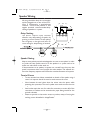
The HFCS1 can be installed in a variety of ceiling environments.The use of the TBCR
(Tile Bridge Support Ring) accessory may be desired for many of these environments.
For suspended ceilings, the use of a TBCR is strongly recommended to
help support and distribute the weight of the speaker.
In new construction installations, the TBCR, installed before sheetrock, acts as a
routing template that ensures an accurate and neat hole for installation.The TBCR
can also be used as a support ring in retrofit applications to better distribute the
speaker’s clamping forces.
1. Begin by cutting a 10-¾" circular hole where the HFCS1 will be installed.If using
a TBCR,then follow its installation instructions for the specific type of environment
the HFCS1 is being installed in.
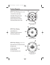
2. Make electrical connections to the pluggable terminal strip and plug it onto the
HFCS1. See Speaker Wiring section.
3. Install terminal cover plates, if necessary or desired, using 4 screws. See the
Terminal Covers section if using conduit or if it is required to secure the speaker
directly to the structure (typically for suspended ceilings).
4. Remove the speaker’s grille. See Speaker Grille Installation & Removal section.
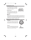
5. Set the power level using the rotary selector switch on the front panel. Refer to
the Selecting Power Levels section for instructions on selecting the power level.
6. Position the swing-out clamps so that they are against the body of the speaker
and insert the speaker into its opening in the ceiling.
7. Tighten the clamps by turning the clamping screws clockwise. Do not over-tighten
the clamps - only tighten until the speaker is fairly snug in the mounting hole. If
using an electric driver, set the clutch on the driver to the lowest setting.
8. Re-install the speaker’s grille. See Speaker Grille Installation & Removal section.
2
IMPORTANT
• There must be a minimum of 11" of vertical clearance between the FRONT
of the mounting surface and any other structure for the speaker to fit. Before
cutting the full hole, use a smaller exploratory hole to determine if there are
any obstructions.
• The edge of the hole must be a minimum of 1-¼" away from any side obstruc-
tions to ensure that they will not interfere with the action of the clamps.
54-2091-01B.qxp 6/18/2004 10:36 AM Page 4


Find Your Products By Category
- TV and Video
- Communications
- Personal Care
- Portable Media
- Computer Equipment
- Home Audio
- Household Appliance
- Car Audio and Video
- Kitchen Appliance
- Fitness & Sports
- Musical Instruments & Equipment
- Power Tools
- Marine Equipment
- Lawn and Garden
- Automotive
- Photography
- Video Game
- Laundry Appliance
- Outdoor Cooking
- Baby
- Cell Phone
Please Login
