
0
Owner's of the Black & Decker Marine Battery 800 Watt Power Inverter gave it a score of 0 out of 5. Here's how the scores stacked up:
Connection to Power Source
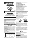
The Power Inverter comes equipped with Battery Clips for connection to a power source.
Connecting to a Power Source Using the Provided Battery Clips
Use the provided Battery Clips (with cables) to connect the Power Inverter directly to the 12 volt power
source as follows:
1.Check to make sure the inverterʼs Power Pushbutton has been pressed OFF (no LEDs are lit) and
that no flammable fumes are present in the installation area.
2.Connect the REDcable to the RED post on the back of the inverter . Connect the RED Battery Clip
to the POSITIVE terminal of the battery.
3.Connect the BLACKcable to the BLACK post on the back of the inverter. Connect the Black Battery
Clip to the NEGATIVE terminal of the battery.
4.Make sure that all connections between cables and terminals are secure.
5.Once properly connected to a 12 volt power source and switched on, the green power LED indicator
lights indicating that the inverter is functioning properly.
CAUTIONS
•Do not use with positive ground electrical systems.
•Reverse polarity connection will result in a blown fuse and may cause permanent damage to the in-
verter.
Note:The majority of modern automobiles, RVs and trucks are negative ground.
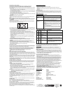
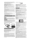
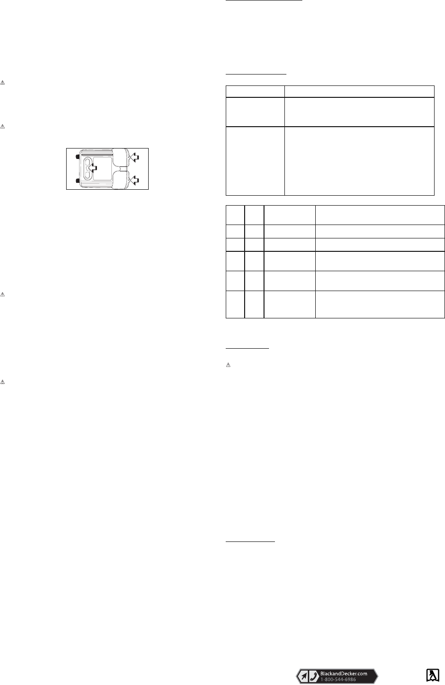
Direct Hardwiring to Power Source (optional connection method; hardware
not included)
WARNING: It is not recommended to install with cables longer than 10ft as this can adversely
effect the operation of your inverter.
As this unit can be directly hard wired it has wall mount features built in to secure it in the desired
location. The diagram below shows you how to do this:
Use #4 AWG wire if the inverter to power source connection is 6 feet or less. For cable lengths up to
10ft use #2AWG wire. In either case, protect the positive (+) wire from shorts by installing a 125 ANL
fuse or circuit breaker close to the DC power source (battery) terminal.
1. Check to make sure the inverterʼs Power Pushbutton has been pressed OFF (no LEDs are lit) and
that no flammable fumes are present in the installation area.
2. Identify the POSITIVE (+) and NEGATIVE (–) DC power source (battery) terminals.
3. Install a fuse holder or breaker close to the POSITIVE (+) terminal of the DC source (battery).
4. Connect a length of wire on one side of the fuse holder or circuit breaker. Connect the other end of
the wire to the POSITIVE (+) terminal of the inverter.
5. Connect a length of wire between the inverterʼs NEGATIVE (–) terminal and the DC power source
NEGATIVE (–) terminal.
6. Connect a short length of wire to the other terminal of the fuse holder or circuit breaker. Mark it
“POSITIVE” or “+”.
7. Connect the free end of the fuse or breaker wire to the POSITIVE (+) terminal of the DC power
source (battery).
8. Insert a fuse appropriate to the inverter in the fuse holder.
9. Test the inverter by turning it on and plugging in a 100 watt lamp or equipment.
10. If the inverter is not properly operating, then refer to the Troubleshooting section of this manual.
CAUTION
•
The cable and fuse sizes given here are a general recommendation. You should always
consult your National Electrical Code prior to beginning each specific installation.
• Loose connectors may cause overheated wires and melted insulation.
• Check to make sure you have not reversed the polarity. Damage due to reversed polarity is
not covered by our warranty.
•Loose connectors may cause overheated wires and melted insulation.
Connection To Load
The Power Inverter is equipped with dual standard North American three-prong type outlets. Plug the
cord from the equipment you wish to operate into the AC receptacle(s). Make sure the combined load
requirement of your equipment does not exceed maximum continuous power.
The Power Inverter is engineered to be connected directly to standard electrical and electronic
equipment in the manner described above. Do not connect the Power Inverter to household or RV AC
distribution wiring. Do not connect the Power Inverter to any AC load circuit in which the neutral
conductor is connected to ground (earth) or to the negative of the DC (battery) source.
WARNING: Do not connect to AC distribution wiring!
Rated Versus Actual Current Draw of Equipment
Most electrical tools, appliances, electronic devices and audio/visual equipment have labels that indi-
cate the power consumption in amps or watts. Be sure that the power consumption of the item to be op-
erated is below 800 watts. If the power consumption is rated in amps AC, simply multiply by the AC volts
(115) to determine the wattage.
Resistive loads are the easiest for the inverter to run; however, it will not run larger resistive loads (such
as electric stoves and heaters), which require far more wattage than the inverter can deliver. Inductive
loads (such as TVs and stereos) require more current to operate than do resistive loads of the same
wattage rating.
For safety reasons, the unit will simply shut down if it is overloaded. To restart the unit, simply unplug all
devices plugged into the unit; disconnect the unit from any 12 volt DC power source; then reconnect the
unit BEFORE plugging the appliance back in.
Inductive loads, i.e. power tools.
Some motors used in power tools, refrigerators and pumps require a very high surge current to start.
This inverter can handle a surge twice it's rated power but some motors require more than this when
started. The inverter will not be harmed if you try to start such a product it will simply shutdown on
overload.
Operation of the 115 Volt AC Outlets
1.Connect the inverter to a functioning 12 volt DC power source as described in this Instruction
Manual. Make sure there is adequate space for proper ventilation of the inverter.
2.Press the Power Pushbutton to turn the unit ON.
3.The green Power LED Indicator will light, indicating a proper connection. If either the yellow amber
low input voltage LED Indicator or red Fault LED Indicator lights, indicating a fault condition exists,
refer to the “Troubleshooting” section of this Instruction Manual.
4.Plug the (110/120 volt AC) appliance into one of the Inverterʼs three-prong AC outlets and operate
normally.
Note:The Inverter will not operate appliances and equipment that generate heat, such as hair dryers,
electric blankets, microwave ovens and toasters.
Remember to disconnect the inverter from any power source when not in use.
Protective Features
The inverter monitors the following conditions:
Low Battery Voltage — This condition is not harmful to the inverter, but could damage the power source,
so the inverter will automatically shut down when input voltage drops below 10.5 ± 0.3 volts DC.
Input Voltage Too High — The inverter will automatically shut down when DC input voltage exceeds
15.5 ± 0.5 volts, as this can harm the unit.
Thermal Shutdown Protection — The inverter will automatically shut down when the unit becomes
overheated.
Overload/Short Circuit Protection — The inverter will automatically shut down when a short circuit occurs.
Operating Tips
The inverter should only be operated in locations that are:
DRY — Do not allow water or other liquids to come into contact with the inverter.
COOL — Surrounding air temperature should ideally be 10-20°C (50-68°F). Keep the inverter away
from direct sunlight, when possible.
WELL-VENTILATED — Keep the area surrounding the inverter clear to ensure free air circulation
around the unit. Do not place items on or over the inverter during operation. The unit will shut down if
the internal temperature gets too hot. The inverter will auto-reset after it cools down.
SAFE — Do not use the inverter near flammable materials or in any locations that may accumulate
flammable fumes or gases. This is an electrical appliance that can briefly spark when electrical connections
are made or broken.
Problem Explanation/Recommendation
Buzzing sound in audio
systems
Some inexpensive stereo systems and boom boxes make a buzzing
sound when operated from the inverter, because the power supply in
the electronic device does not properly filter the modified sine wave
produced by the inverter. The only solution to this problem is to use a
sound system that has a higher quality power supply.
Problem: Television
Interference
The inverter is shielded to minimize interference with TV signals.
However, in some instances, some interference may still be visible,
especially when the TV signal is weak. Try the following to improve
the picture:
1.Move the Inverter as far away as possible from the TV set, the an-
tenna, and the antenna cables. Use a short AC extension cord, if
necessary.
2.Adjust the orientation of the antenna cables, and the TV power
cord to minimize interference.
3.Make sure that the antenna feeding the TV provides an adequate
(snow-free) signal and that high quality, shielded antenna cable is
used.
See ‘Tools-Elec-
tric’
– Yellow Pages –
for Service &
Sales
Imported by
Black & Decker (U.S.) Inc.,
701 E. Joppa Rd.
Towson, MD 21286 U.S.A.
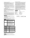
Input
LED
Color
Output
LED
Color
Possible Cause Recommendation
Yellow Low input voltage Start Engine
Red Battery voltage below
10.5 volts
Recharge battery or check DC power supply.
Red Equipment being oper-
ated draws too much
power
• Reduce load to maximum 800 watts.
Red
Inverter in thermal
shutdown condition
Allow inverter to cool down. Ensure there is adequate
ventilation around the load is no more than 800 watts for
continuous operation.
Red
AC output is shorted Unplug the AC appliance. Disconnect the unit from any 12
volt DC power source. Check the appliance cord. Refer to
the Service Information section that follows to contact a
Black & Decker Service Center.
CARE AND MAINTENANCE
Storage
1.Ideal storage temperature range is 0-40°C (32-104°F).
2.Store and use the PI800BB in a cool, dry place with adequate ventilation for all-around air
circulation.
3.Avoid locations that are exposed to heating units, radiators, direct sunlight, or excessive humidity or
dampness.
Fuse Replacement
This inverter is equipped with multiple internal fuses. Normally, these fuses will not “blow” unless there
is a serious problem inside the unit. Internal fuses are replaceable; however, only trained personnel
should attempt fuse replacement. If the unit is damaged during fuse replacement, the warranty may be
voided.
TROUBLESHOOTING
Common Audio/Visual Problems
FAULT CONDITIONS
Red or Yellow Fault LED Indicator Lights
The red Fault LED indicates inverter shutdown from input fault, over temperature fault or overload /
short circuit fault and the yellow Fault LED indicates an input or over-temperature fault.
ACCESSORIES
Recommended accessories for use with your tool are available from your local dealer or authorized
service center. If you need assistance regarding accessories, please call: 1-800-544-6986.
WARNING: The use of any accessory not recommended for use with this tool could be hazardous.
SERVICE INFORMATION
All Black & Decker Service Centers are staffed with trained personnel to provide customers
with efficient and reliable power tool service. Whether you need technical advice, repair, or
genuine factory replacement parts, contact the Black & Decker location nearest you. To find
your local service location, refer to the yellow page directory under "Tools—Electric" or call:
1-800-544-6986 or visit www.blackanddecker.com
FULL TWO-YEAR HOME USE WARRANTY
Black & Decker (U.S.) Inc. warrants this product for two years against any defects in
material or workmanship. The defective product will be replaced or repaired at no charge in
either of two ways.
The first, which will result in exchanges only, is to return the product to the retailer from
whom it was purchased (provided that the store is a participating retailer). Returns should
be made within the time period of the retailerʼs policy for exchanges (usually 30 to 90 days
after the sale). Proof of purchase may be required. Please check with the retailer for their
specific return policy regarding returns that are beyond the time set for exchanges.
The second option is to take or send the product (prepaid) to a Black & Decker owned or
authorized Service Center for repair or replacement at our option. Proof of purchase may be
required.Black & Decker owned and authorized Service Centers are listed under
"Tools-Electric" in the yellow pages of the phone directory.
This warranty does not apply to accessories. This warranty gives you specific legal rights
and you may have other rights which vary from state to state or province to province.
Should you have any questions, contact the manager of your nearest Black & Decker
Service Center. This product is not intended for commercial use.
FREE WARNING LABEL REPLACEMENT: If your warning labels become illegible or are
missing, call 1-800-544-6986 for a free replacement.
LATIN AMERICA: This warranty does not apply to products sold in Latin America. For
products sold in Latin America, check country specific warranty information contained in the
packaging, call the local company or see the website for warranty information.
SPECIFICATIONS
Maximum Continuous Power: 800 watts
Surge Capacity: 1600 watts
Input Voltage: 12.8 volts
Output Voltage: Approx. 115 volt AC RMS 60 Hz
Low Voltage Alarm: < 11.0 volts DC
Low Voltage Shutdown: 10.5 ± 0.3 volts DC
Thermal Shutdown: Automatic
Wave Form: Modified Sine Wave (MSW)
Output Connection: North American Standard Receptacles
Fuses: Internal
Input Cables: Battery clip cables
Operating Temperature: 10-20°C (50-68°F)
Storage Temperature: 0-40°C (32-104°F)
Operating/Relative Humidity: 5-95% non-condensing


Find Your Products By Category
- TV and Video
- Communications
- Personal Care
- Portable Media
- Computer Equipment
- Home Audio
- Household Appliance
- Car Audio and Video
- Kitchen Appliance
- Fitness & Sports
- Musical Instruments & Equipment
- Power Tools
- Marine Equipment
- Lawn and Garden
- Automotive
- Photography
- Video Game
- Laundry Appliance
- Outdoor Cooking
- Baby
- Cell Phone
Please Login
