

0
Owner's of the Bogen Telephone UTI1 gave it a score of 0 out of 5. Here's how the scores stacked up:

Telephone Interface
Wiring Connections & Setup
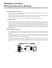
Telephone System Connections
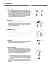
The UTI1 connects to virtually any telephone system: PBX station lines and CO lines, PBX loop start trunk ports,
PBX ground start trunk ports, and page ports.
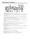
Interface installation consists of setting the slide switches and connecting with modular (RJ11) telephone plugs.Refer
to the appropriate procedure in this section to connect the UTI1 to the telephone system.
Note: In all cases, make sure that power to the UTI1 is disconnected before performing the installation.
Trunk Disconnect
The UTI1 includes a trunk disconnect feature.The purpose of the trunk disconnect feature is to release the UTI1
from the trunk port in the event a user does not hang up the phone properly after making a page. If the UTI1 does
not detect voice for the interface VOX time-out period, or if the interface default timer expires, the UTI1 will
attempt to release from the trunk. When using the trunk disconnect feature with a trunk interface, the PBX must
have disconnect supervision available on the trunk port connected to the UTI1.The trunk disconnect feature is
enabled by default and can be disabled. (Refer to System Programming.) To set the VOX and default timers refer to
System Programming.
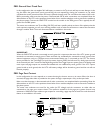
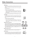
PBX Loop Start Trunk Port
In this configuration, the unit supplies a 24V talk battery and loop current detection.When the unit detects a loop
resistance between Tip and Ring, it activates.When the loop opens, the page ends.The unit follows the status of the
trunk port.
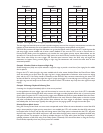
Before configuring the UTI1 for a loop start trunk port, make sure that the power is disconnected and all other
connections are completed. Move the slide switches on the UTI1 to the positions shown below. Use a modular
telephone cord to connect the module to the phone system.
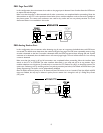
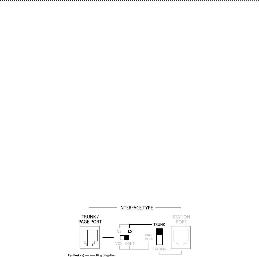
The center two conductors are Tip and Ring (24V DC) and have a specific polarity as shown in the figure to the
right. If the polarity that the trunk requires is opposite, you can use a reversing modular cord to make the
connection or reverse the connection through a modular block.The trunk disconnect feature is available in this
mode.
7


Find Your Products By Category
- TV and Video
- Communications
- Personal Care
- Portable Media
- Computer Equipment
- Home Audio
- Household Appliance
- Car Audio and Video
- Kitchen Appliance
- Fitness & Sports
- Musical Instruments & Equipment
- Power Tools
- Marine Equipment
- Lawn and Garden
- Automotive
- Photography
- Video Game
- Laundry Appliance
- Outdoor Cooking
- Baby
- Cell Phone
Please Login
